The aim is to clarify the questions
- How are the different system functions distributed over
the modules?
-
 What quantities, signals and data are
crossing the interfaces? What quantities, signals and data are
crossing the interfaces?
|

- Frame:
- Stability for approximately 500kg load,
protection.
- Case*:
- outer dimensions:
1.6m x 1.6m x 3.2m, hermetically close,
aerodynamic, optionally futuristic shape.
- Transferrer*:
- automatic transfer of cabin and
plug/unplug of data links, control signals, power supply and air
pipes.
More details on possible realizations of the transferrer systems
can be found on the
MAIT transferrer tour.
- Communication system*:
- for the exchange of global
messages.
- Door*:
- automatic closing and opening, manual
operation if blocked.
- Power supply:
- with battery for backup.
* partly or entirely MAIT standard.
|
A passenger cabin would have additionally:
- User terminal connector
-
- Furniture
-
- Emergency systems:
- emergency break handle, fire sensors,
protection, e.t.c.
- Air conditioning:
- control of air temperature and
distribution.
- Light system:
- with emergency illumination.
- Audio system:
- for messages and costumer supplied audio
source.
- User digital communication system:
- for passengers use
only.
|
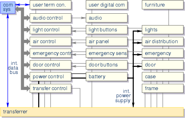
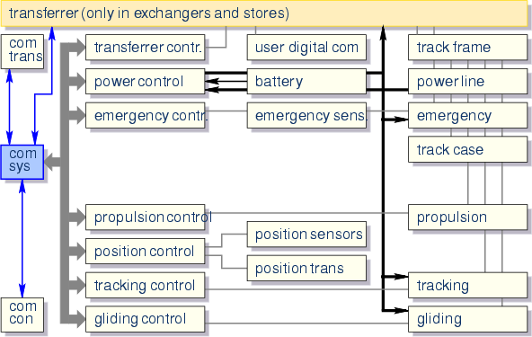
The Block-diagram has the following structure:
- on the left side is the communication system that receives and
sends global messages on the cluster network. It is connected to
an internal data-bus which has (read and/or write) access to all relevant
data of the module.
- in the middle and to the right are the controllers and
actuators of each system, respectively.
This special arrangement in three columns has a particular meaning
for the vertical sub-system structure that will be discussed later on.
Also carriers and track elements are shown in this structure.
The links between the devices are not complete, but they should just
illustrate the essential horizontal and vertical patterns of
connections.
Power lines, data connection, frame (hooks, attachments) and
ventilation go through the transferrer system since it is
responsible for the connection and disconnection of those links from
the carrier, (or the track, if the cabin is put on a stand for waiting,
loading or unloading). Therefore, the transferrer device has its
counterparts on the carrier and on some track elements.
The transferrer as a whole is defined as the set of all transferrer
systems (of cabins, carriers, and track) that are involved in a
particular transfer process (carrier-carrier, carrier-track).
More details on possible realizations of the transferrer systems
can be found on the
MAIT transferrer tour.

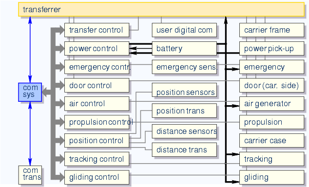
- Frame:
- Stability for approximately 700kg load,
protection.
- Case:
- aerodynamic shape with cabin,
optionally futuristic shape.
- Transferrer*:
- automatic transfer of cabin and plug/unplug
of data links, control signals, power supply and air pipes.
More details on possible realizations of the transferrer systems
can be found on the
MAIT transferrer tour.
- Communication system*:
- with communication link to
track for the exchange of global messages.
- Door (carrier side):
- blocks door when carrier is moving.
- Power supply:
- with power pick-up from track and battery.
- Emergency systems:
- emergency break, collision protection, e.t.c.
|
- Air generation:
- provides warm and cool air (climate
dependent).
- User digital communication system:
- communication link to track.
- Propulsion system:
- carrier engine with propulsion control.
- Positioning system:
- includes all sensors and signal
processing for the evaluation of relative and absolute carrier position.
- Tracking system:
- keeps the carrier on the desired path
and branches, if necessary.
- Gliding system:
- are all components that keep the carrier moving on the track (wheels, magnetic fields, pressurized air e.t.c.)
* partly or entirely MAIT standard.
|

- Frame:
- entirely technology dependent.
- Case:
- if possible, futuristic shape.
- Transferrer*:
- only for stops and storage elements.
More details on possible realizations of the transferrer systems
can be found on the
MAIT transferrer tour.
- Communication system*:
- with communication link to
carriers and neighbour track elements. Exchange of global
messages.
- Power supply:
- provides power to carriers and neighbour
track elements.
- Emergency systems:
- emergency stop, evacuation systems, e.t.c.
|
- User digital communication system:
- communication link
between carrier and a third party base station.
- Propulsion system:
- track part, technology
dependent.
- Positioning system:
- includes all sensors and signal
processing for the evaluation of all carrier positions on the
specific element.
- Tracking system:
- track part, technology dependent.
- Gliding system:
- track part, technology dependent.
* partly or entirely MAIT standard.
|
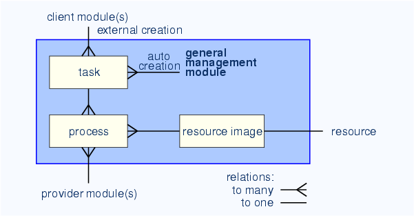
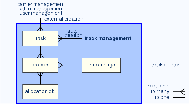
Core data structure of a general management module
- Task:
- is updating, iterating and controlling the
states of one or more processes. Tasks can be ``created'' by
- an external client module (pull strategy) or
- by the management module itself (push strategy).
- Process:
- data, containing all information of target and
real states of one module during a process. The concerned module
states can be
- the resource image of the own management module or
- an external provider module.
|
- Resource image:
- contains data of the resource that is
controlled by the concerned management module (user, cabin, carrier
or track cluster) such as
- state: for example availability, rough position, e.t.c
- scheduling data: estimated available time (and location) in the
future. The scheduling time is occupied by one ore more processes.
The resource image data is regularly updated through the cluster net
and intra net.
|
Concerning the control of resources, there is a general strategy: at
any time, each resource needs to be controlled by a process and the
process is coordinated with other processes within a task. This is to
ensure that the movement of each module is embedded in a globally
optimized action.
For example, it may happen that a cabin stands still because there
is no user management that gives an order to the cabin management.
In this case the cabin management needs to create a task for the
concerned cabin (= auto-creation) and moves it to a point in the
network where the probability to pick up a new customer is higher.
core data structure of a general management module
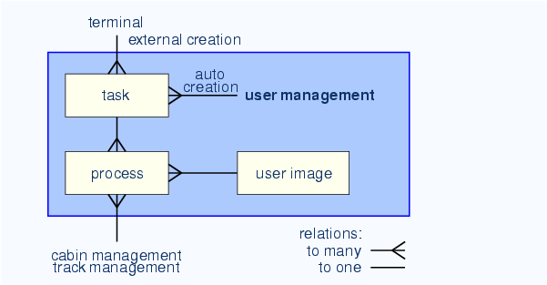
core data structure of user management
core data structure of cabin management
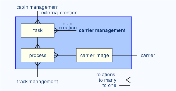
core data structure of carrier management
Core data structure of track management
The track management has additionally an allocation database , where
user-, cabin-, carrier- and track management can
- announce availability of empty cabins, carriers and track
capacity .
- find and allocate empty cabins, carriers and track capacity.
All announcements and allocations are within the concerned track
cluster, which allows all management modules for a spatial search of
resources trough the MAIT network.
|
core data structure of track management