


|
| Next: How to use MAIT ? |
Definition by the Advanced Transit Association, ATRA (see
http://advancedtransit.org/)
Personal Rapid Transit (PRT)
on demand.
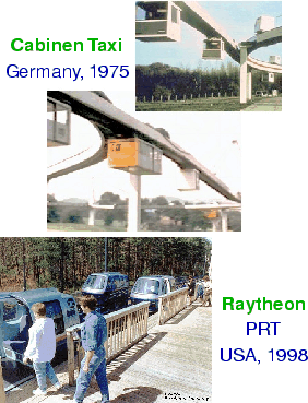
Higher capacity by reducing headways
![\includegraphics[width=90mm]{fig_car_jat1.ps}](img16.gif)
Motor-way at its capacity limits![]()
This impressive visual pictures have been scanned form an article by W. A. Wilde [6] and improved by image processing.
![\includegraphics[width=90mm]{fig_car_jat2.ps}](img17.gif)
![]() removing the cars
removing the cars ![]()
![\includegraphics[width=90mm]{fig_car_jat3.ps}](img18.gif)
![]() reducing the space between people
reducing the space between people![]()
![\includegraphics[width=90mm]{fig_car_jat4.ps}](img19.gif)
![]() putting people into PRT vehicles.
putting people into PRT vehicles.
Reasons for high space-efficiency
of PRT systems
(down to fractional seconds).
(approx. 1.50-2.00m)
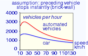
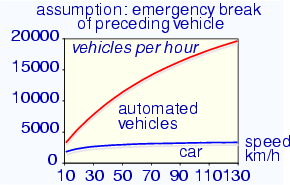
The carrying capacity, expressed in persons per hour is not an
obvious quantity to determine, as it depends on a large number of
parameters and assumptions. The prime systematic difference
between the manually driven car and an automated system is that the
car has a much longer break actuation time. The break actuation time
is the time between the occurrence of a breaking man![]() uvre of the
preceding vehicle and the actuation of the break. This time is for
cars approximately 0.8s and for automatic detection and
breaking systems in the range of milli-seconds.
The minimum time headway
uvre of the
preceding vehicle and the actuation of the break. This time is for
cars approximately 0.8s and for automatic detection and
breaking systems in the range of milli-seconds.
The minimum time headway ![]() , that is the time that passes
between two successive vehicles must
be [7]
, that is the time that passes
between two successive vehicles must
be [7]
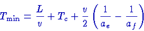
| parameter | symbol | value |
| Vehicle length | L | 3m |
| Line speed | v | 10-130km/h |
| Break actuation time | Tc | 100ms |
| Emergency deceleration | ae |
0.9g rubber on asphalt 0.65g rubber on concrete 0.2g rubber on ice 0.5g acceptable without safety belt |
| Failure deceleration | af |
ae if preceding vehicle does emergency breaking |
For the first simulation we assumed that the emergency and failure
decelerations are
ae=af=0.5g.
For the second simulation we assumed that the emergency decelerationae=0.9g and failure deceleration
![]() m/s2 (instant stop or brickwall).
For the car we assumed a reaction time of Tc=800ms.
m/s2 (instant stop or brickwall).
For the car we assumed a reaction time of Tc=800ms.
For comparison, a light rail train system (or metro) with 6 wagons per train and 100 passengers per wagon, where one train arrives each 5 minutes has carrying capacity of 7200persons per hour. However, in contrast with rail, MAIT is a distributed transport network and therefore does not need to concentrate the traffic onto lines. Because a MAIT guideways are smaller and more cost-effective than rail, it is possible to install more tracks to cover a certain area. In conclusion, the capacity of MAIT guideway does not need to be as high as the one of a metro line.
The performance difference between the two graphs is due to different safety assumptions: The second graph shows the performance if present train safety criteria were applied ("brick-wall criteria"). However, excluding the case that a vehicle is able to stop instantly, but decelerates at the maximum emergency deceleration, the throughput of the automated system can be improved considerably as shown in the top figure. In conclusion: safety legislation determines significantly the capacity of an automated network.
Options to integrate guideways into the city architecture:
Visual impact of PRT-guideways
![\includegraphics[width=60mm]{fig_car_ultra.ps}](img28.gif)
![\includegraphics[width=60mm]{fig_visual2_html.ps}](img29.gif)
Note that unidirectional MAIT guideways have a width of only 1.50m and are comparable in size to larger pedestrian walkways or ``sky-ways''. A city with streets that are protected from sun and rain (such as Bologna, Italy or Bern, Switzerland) is more welcoming to both visitors and inhabitants. Another option are road carriers that do not need any visible guideway and that are slow and can share space with pedestrians. The top guideway photo shows an the ULTra system [8] in an urban environment. The bottom guideway photo (thanks to Dennis Manning) is similar in dimensions to the Taxi2000 PRT [9] system, but this is not an automated Personal Rapid Transit (PRT) system. It is has been built in 1973 by Universal Mobility which was sold to TGI which was in turn sold to Bombardier. In 1996 it was given a refurbishing by Lamoreaux McClendon & Associates. The vehicle is shown in the frame of the lower photograph. Differences between this system and the projected Taxi2000 system:
![\includegraphics[width=50mm]{fig_m5_before.ps}](img32.gif)
![\includegraphics[width=50mm]{fig_parking_before.ps}](img33.gif)
![\includegraphics[width=50mm]{fig_m5_after.ps}](img34.gif)
![\includegraphics[width=50mm]{fig_parking_after.ps}](img35.gif)
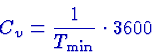
Park shuttle [10] is engineered by Frog Navigation
Systems, the Netherlands and Serpentine by Serpentine SA,
Switzerland [11].
Automated Guided Vehicle Systems (AGVS)
Properties:
Technical Problems:
For more information on advanced transportation technologies, please
consult Jerry Schneider's Innovative transportation web
site: [12].
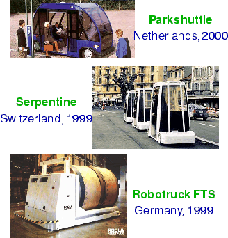
Future Carrier Technologies
|
| Next: How to use MAIT ? |
|
|
MAIT home |
Last updated: 2001-05-30 by webmaster@maitint.org |